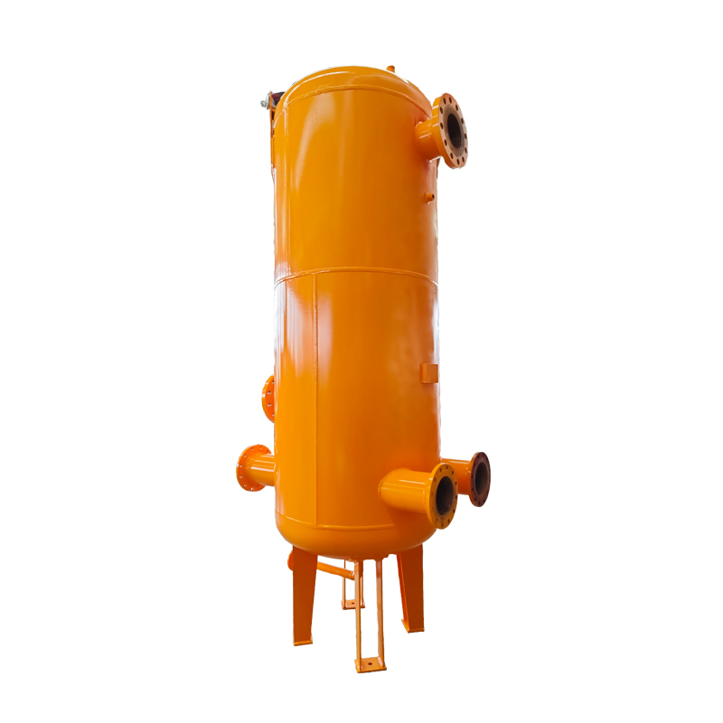
The cyclone purifier integrates the centrifugal and filtering separation technology, to avoid the liquid film cutting, re-atomization, liquid entrainment, entrainment, suction, and secondary crushing. In the separation process, gas enters into the cyclone for rotation under a certain pressure and flows downwards along the axial direction.
Under the action of centrifugal force, large amounts of liquid and solid particles are dumped to the lower part of the cylinder wall, and the gas discharges from the cyclone. In the flow process, the circulation section increases gradually, and speed decreases gradually, and liquid and solid are discharged along the wall, which achieves the gas and liquid or gas and solid separation process.
The gas enters into the outlet pipe after the gas and liquid or gas and solid separation, and flows into the mist catcher for secondary separation. The small drops in gas are condensed into large drops, which fall down depending on their own weight, and into the liquid trap cavity through conduction pipe. Finally, separated solid particles and liquid are discharged from the drain outlet, and the separated gas from the gas outlet.
Design standard: GB 150-2011 Pressure vessel
Structure: Vertical and horizontal types
Connecting flange standard: HG/T20592 ~ 20635- 2009 or ANSI B16.5, etc.
Material standard: Steel plate: GB7l3-2008Q345R
Forging parts: NB/T47008-20l0 l6Mn
Design pressure: <10MPa
Design temperature: -40℃ ~ +80℃
Pressure drop: <0.05Mpa
Separation accuracy: ≥3 - 5μm of solid particles can be removed; and ≥8-10μm of liquid particles can be removed.
Separation efficiency: In the operating point, the efficiencies of separation for solid and liquid particles are both up to 99%; in the operating point of ±15%, the separation efficiency is 97%.
Flow fluctuation range: 40%tol20%
Primary separation of natural gas and coal-bed gas; removal of desiccant particles from lower drying bed; removal of catalyst fines of lower catalyst bed; for metering and regulating stations; for urban gas distribution systems.
|
Basic Structure and Size of Cyclone Purifier (mm) |
||||||||||||||||||||
|
SN |
Cylinder diameter
|
Inlet and outlet diameter |
Structure size (mm) |
Nozzle table |
||||||||||||||||
|
L |
L1 |
L2 |
L3 |
L4 |
L5 |
L6 |
L7 |
D1 |
1 |
2 |
3 |
4 |
5 |
6 |
7 |
8 |
9 |
|||
|
1 |
500 |
100 |
4105 |
2350 |
300 |
800 |
250 |
650 |
255 |
200 |
570 |
50 |
100 |
40 |
100 |
50 |
50 |
150 |
20 |
20 |
|
2 |
600 |
150 |
4302 |
2410 |
300 |
800 |
250 |
650 |
375 |
200 |
680 |
50 |
150 |
40 |
150 |
50 |
50 |
150 |
20 |
20 |
|
3 |
700 |
200 |
4328 |
2508 |
300 |
900 |
250 |
650 |
415 |
250 |
795 |
80 |
200 |
40 |
200 |
50 |
50 |
200 |
20 |
20 |
|
4 |
800 |
250 |
4515 |
2568 |
300 |
1000 |
280 |
700 |
475 |
250 |
930 |
80 |
250 |
50 |
250 |
50 |
50 |
200 |
25 |
25 |
|
5 |
900 |
300 |
4620 |
2640 |
350 |
1000 |
280 |
700 |
535 |
250 |
1140 |
80 |
300 |
50 |
300 |
50 |
50 |
400 |
25 |
25 |
|
6 |
1000 |
350 |
4710 |
2725 |
350 |
1000 |
280 |
700 |
570 |
250 |
1150 |
80 |
350 |
50 |
350 |
50 |
50 |
400 |
25 |
25 |
|
7 |
1200 |
400 |
4785 |
2810 |
370 |
1000 |
300 |
850 |
635 |
300 |
1250 |
80 |
400 |
80 |
400 |
50 |
50 |
450 |
25 |
25 |
|
8 |
1300 |
400 |
4805 |
2900 |
370 |
1050 |
300 |
850 |
675 |
300 |
1350 |
80 |
400 |
80 |
400 |
50 |
50 |
500 |
25 |
25 |
|
9 |
1400 |
400 |
4860 |
2985 |
370 |
1050 |
300 |
850 |
725 |
300 |
1460 |
80 |
400 |
80 |
400 |
50 |
50 |
500 |
25 |
25 |
|
10 |
1500 |
400 |
5035 |
3135 |
425 |
1100 |
300 |
900 |
775 |
300 |
1570 |
80 |
400 |
80 |
400 |
50 |
50 |
500 |
25 |
25 |
|
11 |
1600 |
400 |
5165 |
3520 |
425 |
1100 |
300 |
900 |
900 |
300 |
1780 |
80 |
400 |
80 |
400 |
50 |
50 |
500 |
25 |
25 |

