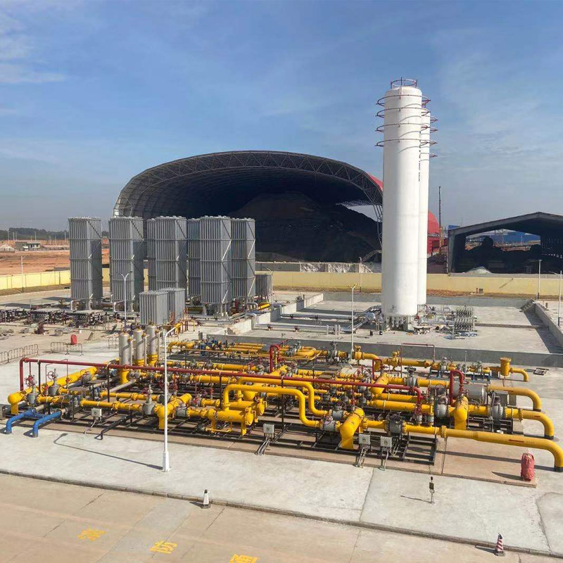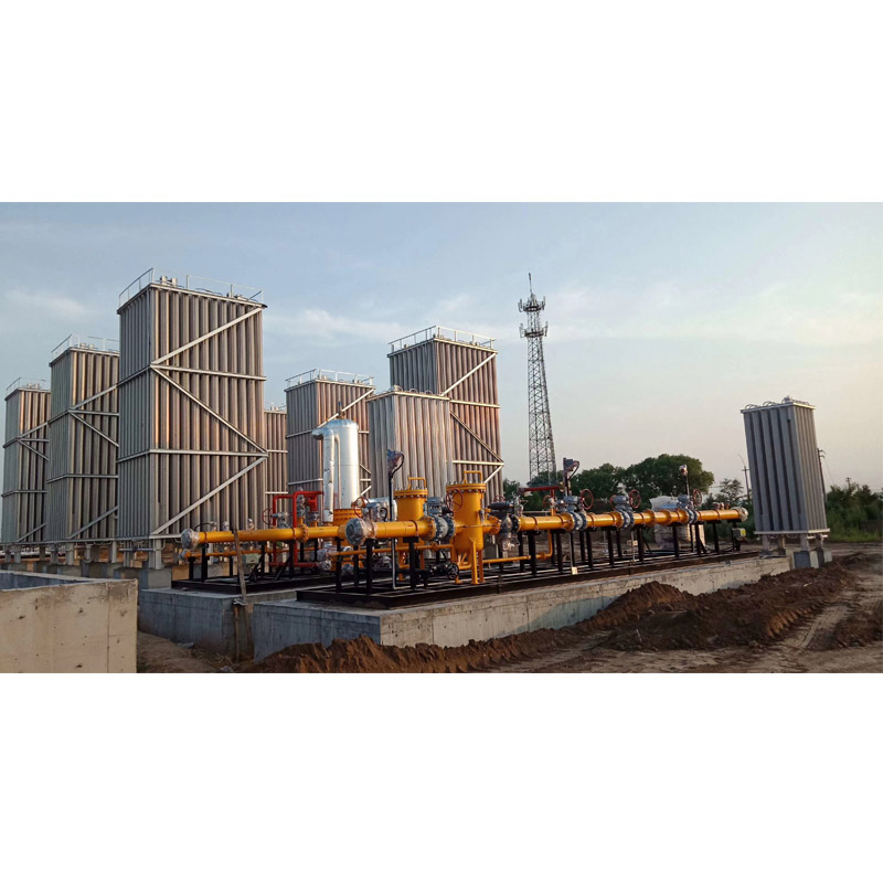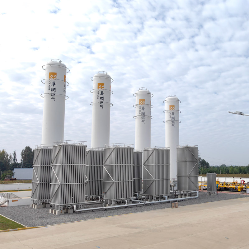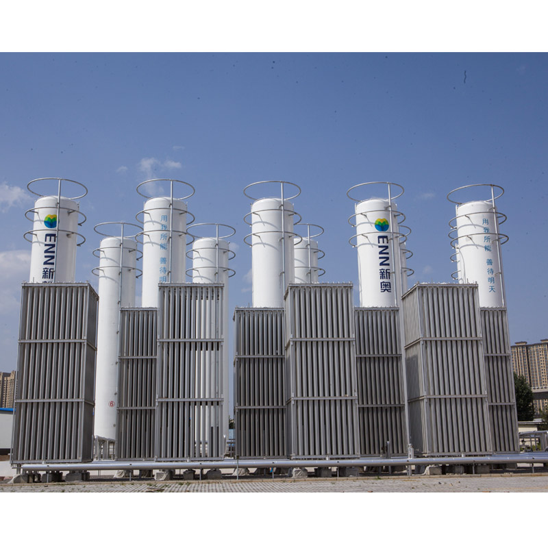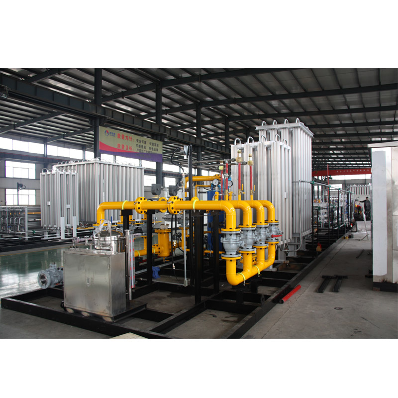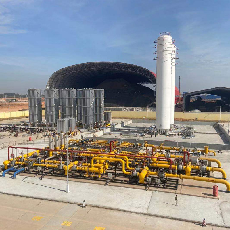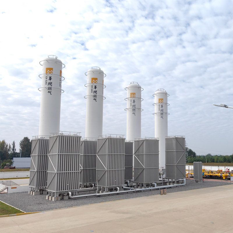
The LNG has become the main gas source or transition gas source for cities which fail to use the pipeline gas currently, and also is the supplemental gas source or peak load gas source for many cities which use the pipeline gas. The LNG gasification station is a LNG satellite station having receiving, storage and distribution functions, and also an intermediate regulation site for towns or gas enterprises to transfer the LNG from manufacturers to users.
The LNG gasification station has been gradually built in many economically developed and energy-deficient medium and small cities in China's South-East coastal areas depending on its advantages including short construction period and quickly meeting the gas market’s demands, becoming a permanent gas supply facility or a transition gas supply facility before arrival of the pipeline gas.
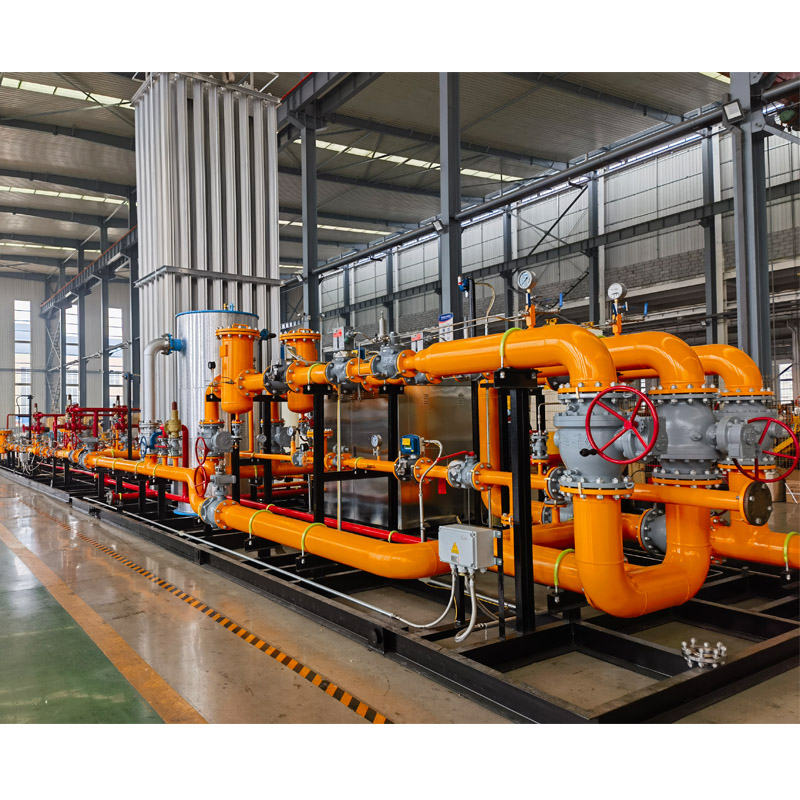
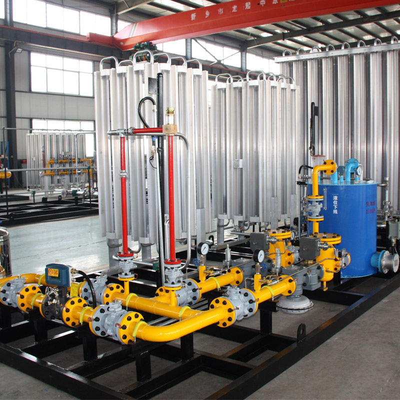
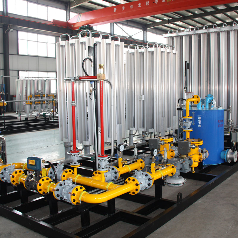
The LNG gasification station is generally assembled according to reasonable technology, integrating the LNG low temperature storage tank (cylinder or tanker), air-heated vaporizer, pressure reducing valves, chemical dosing system and metering system. It has features including compact structure, small volume and high automation degree.
The LNG is transported to gasification stations by a tanker. Rise the pressure in the tanker by means of a LNG unloading pressurizer, and deliver the LNG in the tanker to the LNG low temperature storage tank. When the LNG is discharged from the LNG storage tank, rise the pressure in the storage tank by means of the storage tank pressurization system, then open the liquid phase outlet valve of the storage tank, deliver the LNG in the storage tank to the vaporizer through pressure difference and then deliver it to the municipal gas pipeline network by working procedures such as pressure regulation, metering and odorization.
When the outdoor ambient temperature is low and the natural gas temperature at the air-heated vaporizer outlet is below 5℃, it is necessary to connect a water bath heater to the air-heated vaporizer outlet to heat the vaporized natural gas.
- ♦No energy consumption, no contamination, and low later operating costs;
- ♦Optional dimensions;
- ♦Optimal design, meeting the vaporizationquantity requirement, cost reduction, low pressure drop, and no bias;
- ♦The equipment is beautiful and firmby the connection of an aluminium“bridge”, effectively eliminating the stress caused due to heat-expansion and cold-contraction;
- ♦All equipment components are made according to JB/T2549-94Technical Specification for Manufacturing of Aluminum-made Air Separation Plantsand Q/OYN01-2017 Enterprise Standard;
- ♦An auxiliary heateris configured, ensuring the NGoutlet temperature;
- ♦Safety valve open pressure: 0.84Mpa;
- ♦Operating pressure: 0.02-0.8Mpa;
- ♦Vaporizationcapacity: 20-7000Nm³/h;
- ♦Complete safety protection function, ensuring safe and reliable operation.
-
Main Safety Parameters
Model
LNG-
200
LNG-
300
LNG-
400
LNG-
500
LNG-
600
LNG-
800
LNG-
1000
LNG-
1200
LNG-
1500
LNG-
2000
LNG-
2500
LNG-
3000
LNG-
4000
LNG-
5000
LNG-
5000
LNG-
10000
Design Pressure (MPa)
1.6
Design Temperature(℃)
Before gasification: -196~ +50;
After gasification: -20~ +50;
Operating Pressure (MPa)
Before pressure regulation: < 0.6;
After pressure regulation: < 0.3;
Strength Pressure Test (MPa)
2.4
Airtight Pressure Test (MPa)
1.92
Outlet Pressure (MPa)
≤0.4
Operating
Temperature (℃)
Before gasification: -162~ +50;
After gasification: -20~ +50
Rated Supply (Nm³/h)
200
300
400
500
600
800
1000
1200
1500
2000
2500
3000
4000
5000
8000
10000
Inlet Size (mm)
Unloading liquid phase: DN50;
Unloading gas phase: DN40;
Unloading pressurization: DN32
Outlet Size (mm)
50
80
80
80
80
100
100
100
100
150
150
150
200
200
250
250
Recuperator Power (KW)
4.5
7.5
7.5
7.5
10.5
12
15
18
22.5
30
37.5
45
60
90
120
150
Recuperative Voltage
(V)
380
Odorization Machine Voltage (V)
220
Flowmeter Accurccy
(level)
1.0-1.5

